


Mikorist
-
Broj sadržaja
46952 -
Na DiyAudio.rs od
-
Broj dana (pobeda)
653
Content Type
Profiles
Forum
Blog
Kalendar
Sve objavljeno od Mikorist
-
jbt kako se ovo čuje.... i to direkt slušam sa youtube
-
OPA1612 me najviše podseća na Dynaco PAT-5 http://www.tonepublications.com/old-school/dynaco-pat-5-preamplifer/ tako da ga ne vadim... isti taj zvuk.... mogu da ubacim još dva samo napred. naravno - dati mu fore da se usvira.... 100 sati najmanje
-
-

Zanimljive, smešne i čudne fotografije
Mikorist je odgovorio/la Mikorist's temus u Muzika , Film i Fotografija

-
Zanimljive, smešne i čudne fotografije
Mikorist je odgovorio/la Mikorist's temus u Muzika , Film i Fotografija
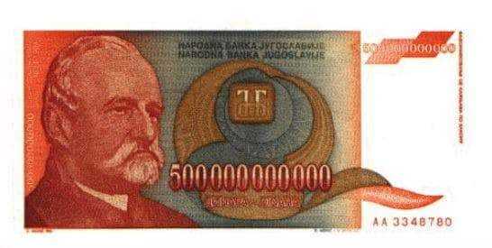
ma bre odvalio sam broj pravi je 313.563.558 ali je godišnja inflacija 352.459.275.105.195 odsto. https://www.blic.rs/biznis/gorko-secanje-na-januar-1994-kako-smo-ziveli-kada-je-od-cele-plate-mogla-da-se-kupi/zk5gqjx
-
više volim njihove komedije https://www.imdb.com/title/tt1286126/ znači bukvalno sam plakao - jedan gif iz filma
-
Zanimljive, smešne i čudne fotografije
Mikorist je odgovorio/la Mikorist's temus u Muzika , Film i Fotografija
ma dosta i JBL iz Kernika -
Zanimljive, smešne i čudne fotografije
Mikorist je odgovorio/la Mikorist's temus u Muzika , Film i Fotografija
-
Zanimljive, smešne i čudne fotografije
Mikorist je odgovorio/la Mikorist's temus u Muzika , Film i Fotografija
Inflacija 4. januara 1994, u odnosu na 1993, iznosila je 550.000.000.000.000.000.000%. Rast kursa nemačke marke iznosio je 670.000.000.000.000.000.000%. Cene su se povećavale po stopi od 2% na sat ili 0,029% u minuti, a u toku meseca rast cena je bio 313.563.558%.
-
https://www.imdb.com/title/tt0087803/
-
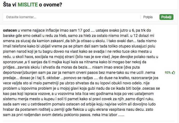
Vredelo je svaki put kad me je neko gađao nekim uređajem sa foruma
-
Zanimljivi & smešni na You Tube
Mikorist je odgovorio/la Leonardo's temus u Muzika , Film i Fotografija
-
Zanimljivi & smešni na You Tube
Mikorist je odgovorio/la Leonardo's temus u Muzika , Film i Fotografija
kakakv kralj... pa ovaj lik je otkrovenje -
Vala ubacio sam 1612 i ne menjam više...... sve je to prelest
-
Cena često nema veze sa zvukom.... Recimo na D10 bolje paše OPA1612 nego neki opamp od 45$ ....(skuplje zvuči) a nema logike ni kad se meri a nema ni veze na grafikonu šta je bolje zvučno....
-
Ja sam mislio da je bakarni lim keva.... Staviš pregrade od 1cm bakra za toruse i zdravo fluks p.s. Msm i da je 1T fotra i da toliko izlazi... ona bakarna gromada na videu će da je zaustavi
-
ko u japanu... sve haj end... od bandera, preko semafora do kućnih utičnica.
-
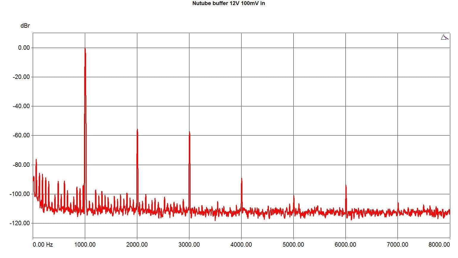
i da traje 50 godina ako se koristi Korg Nutube http://www.pmillett.com/Nutube_buffer.html bafer prva liga ide na -100db
-
Zanimljive, smešne i čudne fotografije
Mikorist je odgovorio/la Mikorist's temus u Muzika , Film i Fotografija
-
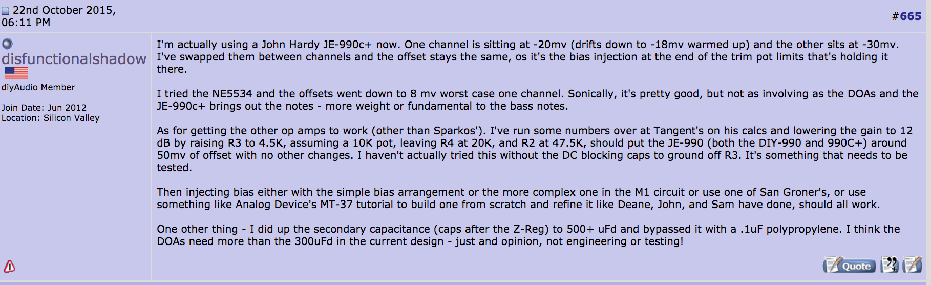
Neki lik na BIG DIY je ovaj 990 stavljao u Sapphire pojačalo za slušalice umesto OPA134 https://www.diyaudio.com/forums/headphone-systems/196149-rjm-audio-sapphire-desktop-headphone-amplifier-67.html#post4492023 http://phonoclone.com/diy-sapp.html Kapiram da može dide i u DAC
-
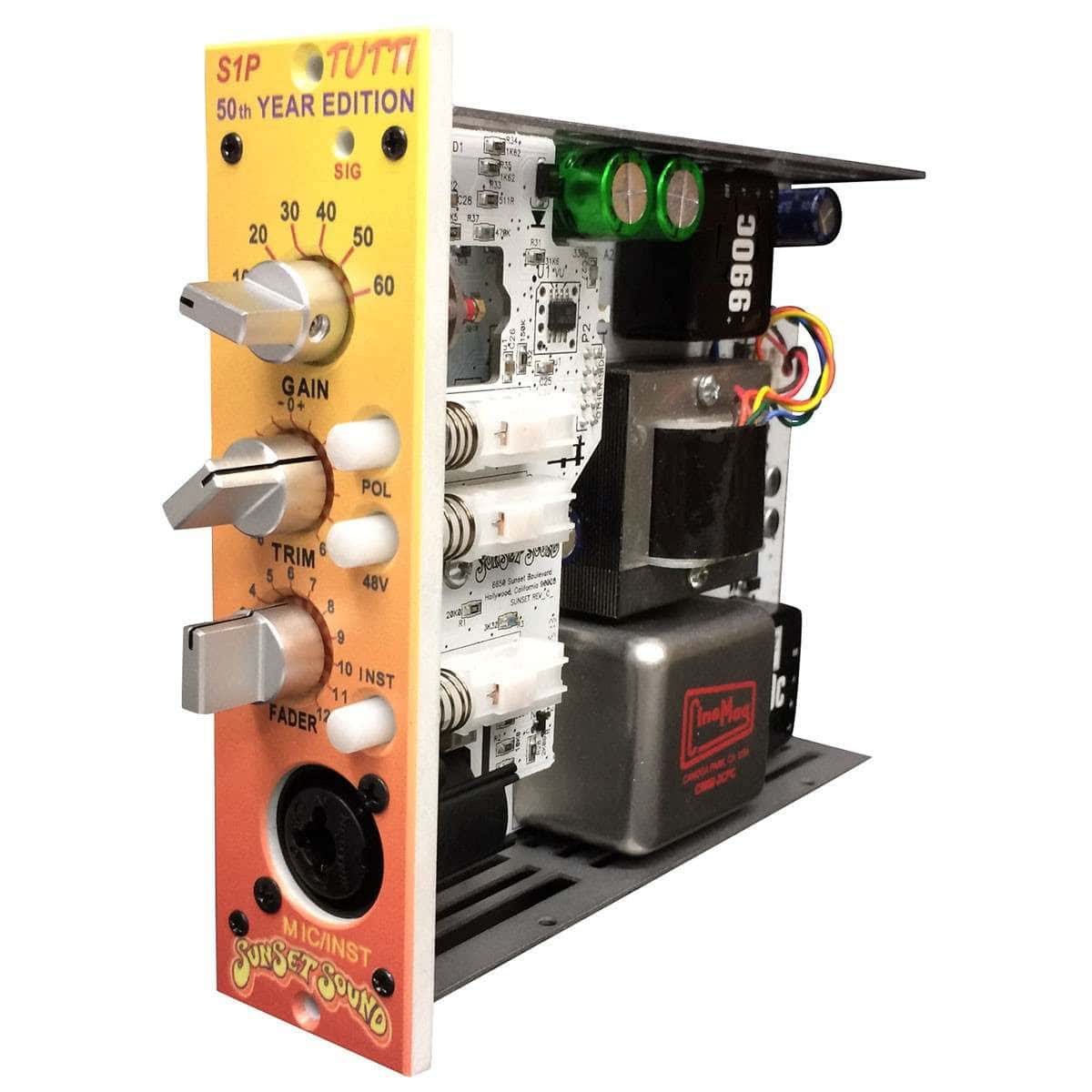
Ili ovaj što je proslavio 50 godina http://www.johnhardyco.com/pdf/990.pdf http://www.johnhardyco.com/ U kombinaciji sa Jensen - Cinemag trafoima u phono i mic preampovima
-
http://www.synaesthesia.ca/LNschematics.html
-
-
Zanimljive, smešne i čudne fotografije
Mikorist je odgovorio/la Mikorist's temus u Muzika , Film i Fotografija


-
Trenutno na sajtu 0 članova, 0 Skrivenih, 91 Gosta (Pogledaj celu listu)
- There are no registered users currently online
-
Forumska statistika
9.2k
Ukupan broj tema452.1k
Ukupan broj objava -
Statistika članovȃ
3017
Svi članovi5071
Najviše na sajtu