


Zen Mod
-
Broj sadržaja
40598 -
Na DiyAudio.rs od
-
Broj dana (pobeda)
612
Content Type
Profiles
Forum
Blog
Kalendar
Sve objavljeno od Zen Mod
-
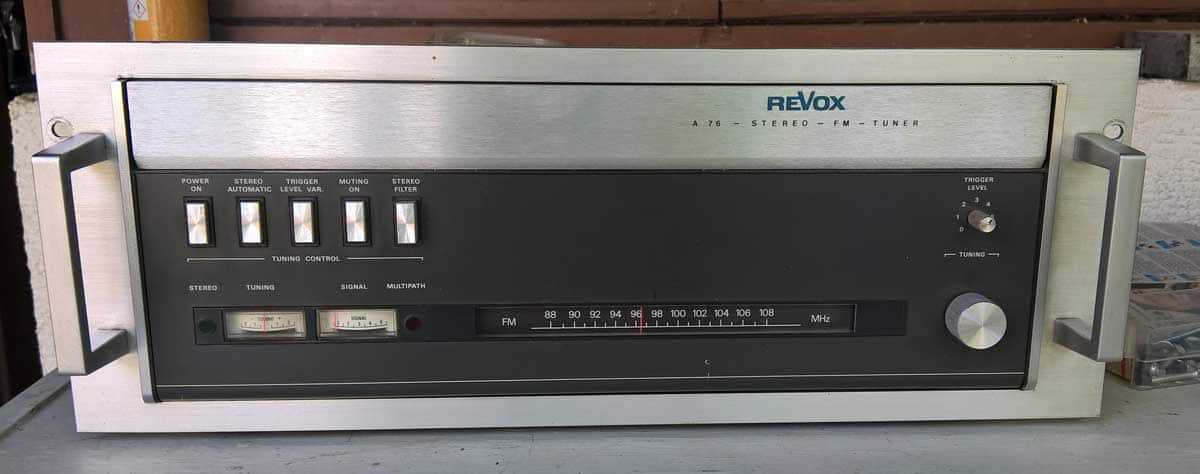
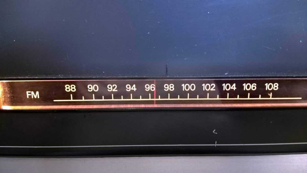
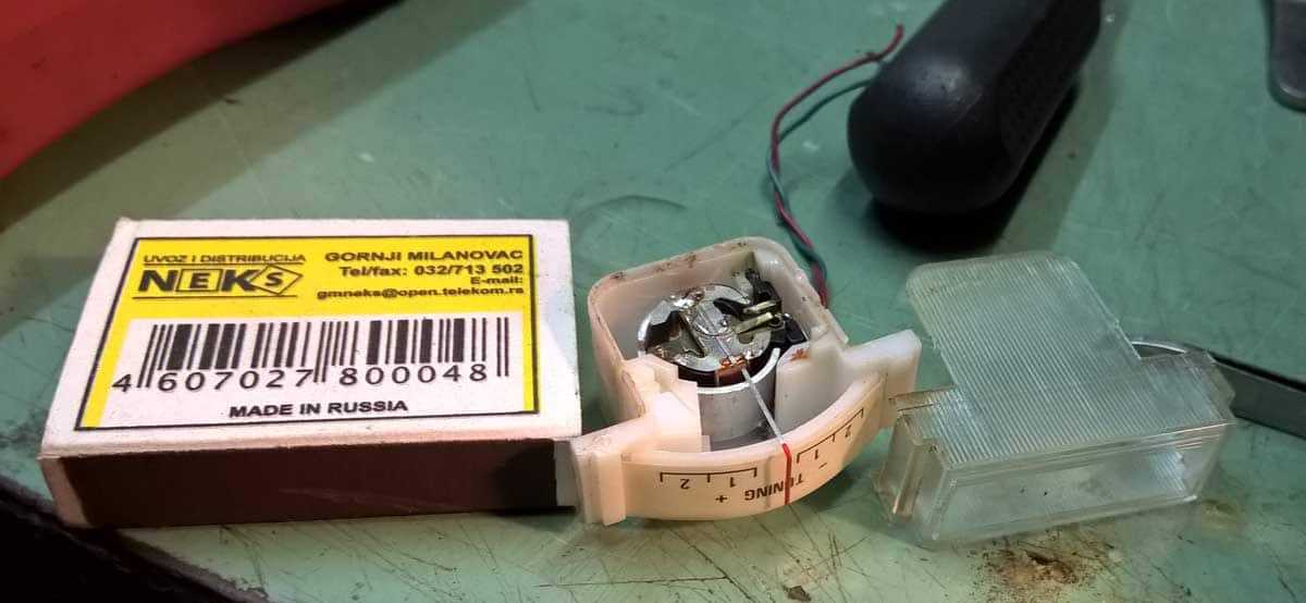
to sto se vidi na cajgerima je sa par krokodilki* umesto antene *zica od 30cm sa stipaljkama na krajevima
-
Dakle - mali svira ko veliki . Doktor Kenwood-a moze da turi u kufinju , a moja dva A76 ce spavaju dok ne stignu cajgeri ....... do tad ce sviri FT440 u radionici. Hasta la vista bejbe info - prikazanih 96.5MHz je RBG2/3 na mom podrucju . Mozda Doktoru nece odgovarati sto sam super lepkom blokirao skalu ......... al kad nisam ni pomislio da je u Prestonici mozda drugojacije
-
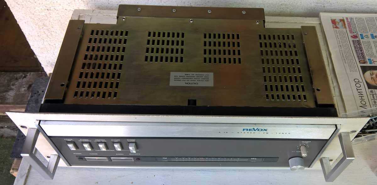
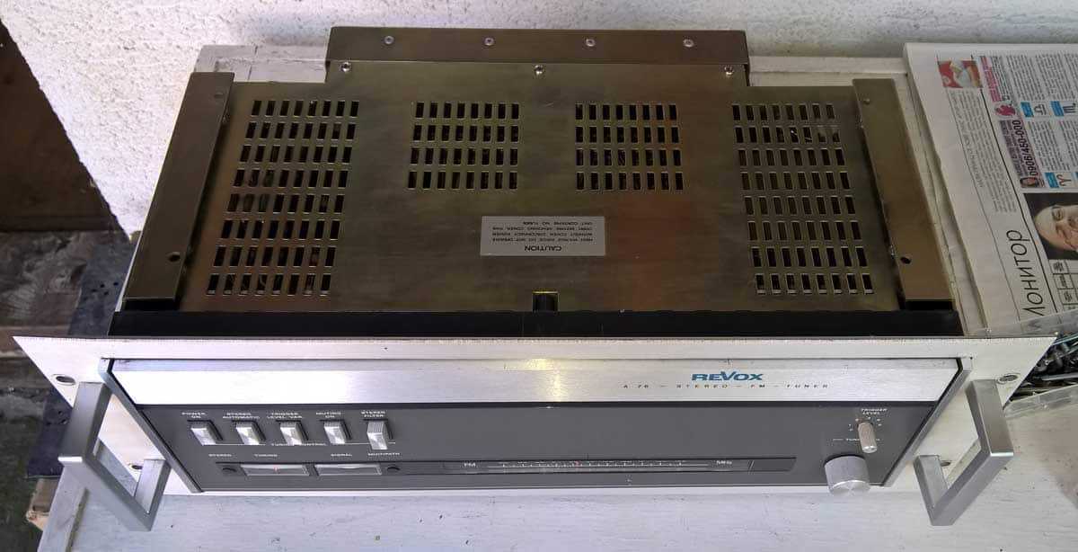
Onda jos koja slikica

-
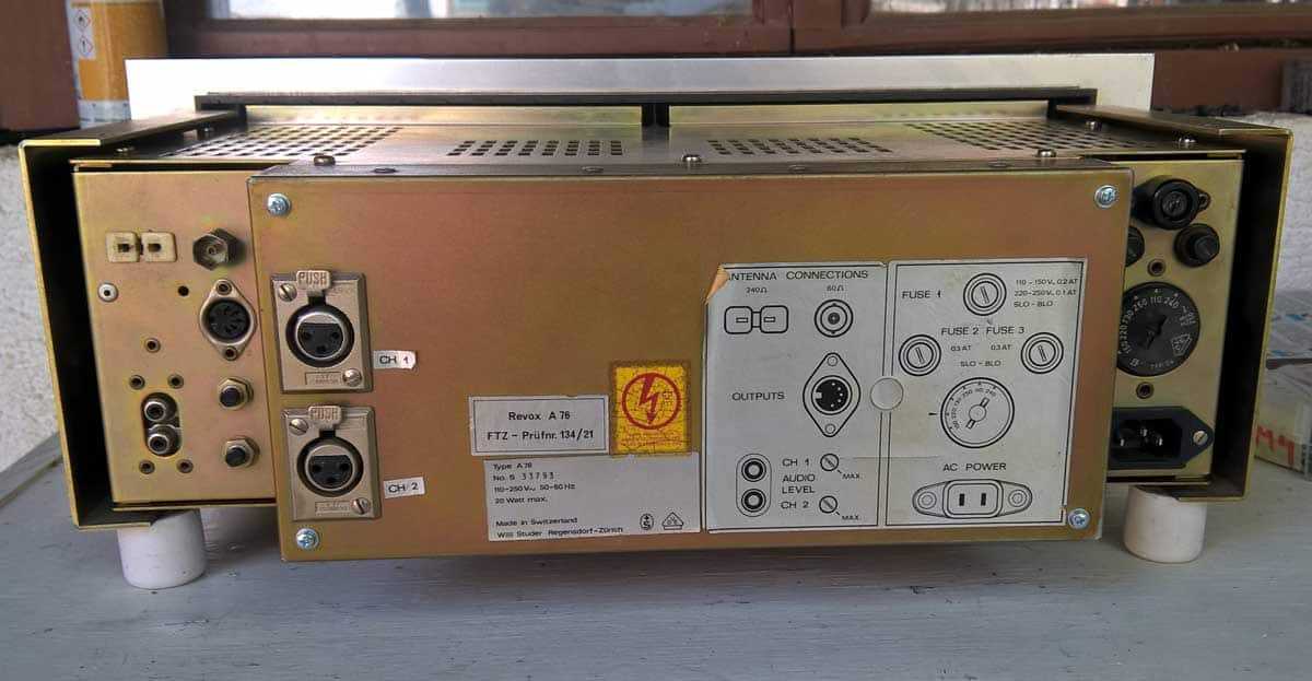
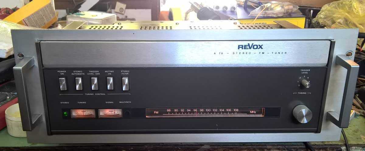
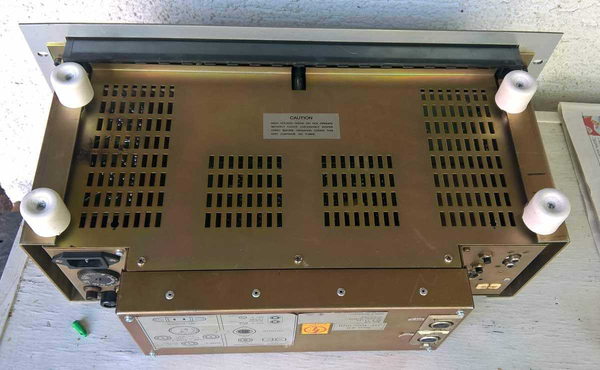
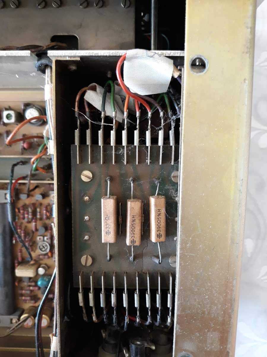
Vec pripremljeni i oprani elementi za zatvaranje ........ Kupljene nogice ( odbojnici za vrata , sta drugo !?) , izbusene rupe na donjem poklopcu , i ta opcija vazi kad nema Rack Mount-a; Medjutim , kad se stavlja Rack Mount - po Doktorovoj izricitoj zelji , isti (Rack Mount , ne Doktor) se bukvalno navlaci na tuner ( ili se tuner spusta u rack mount ) i u tom slucaju su nogice na bottom plate prosto no go. U tom slucaju se nogice pozicioniraju na srafove koji inace stezu rack mount na tuner , u donjoj zoni ..... srafovi na slici privremeni - u ponedeljak prodavnica , ce nabavimo picikato. Obratiti paznju - da bi sve bilo u skladu - za Doktora bele nogice ! Da mu se slazu sa bele carapice i bele klompe .
-
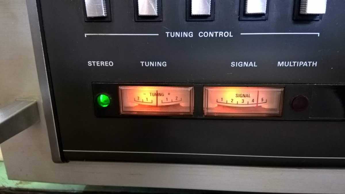
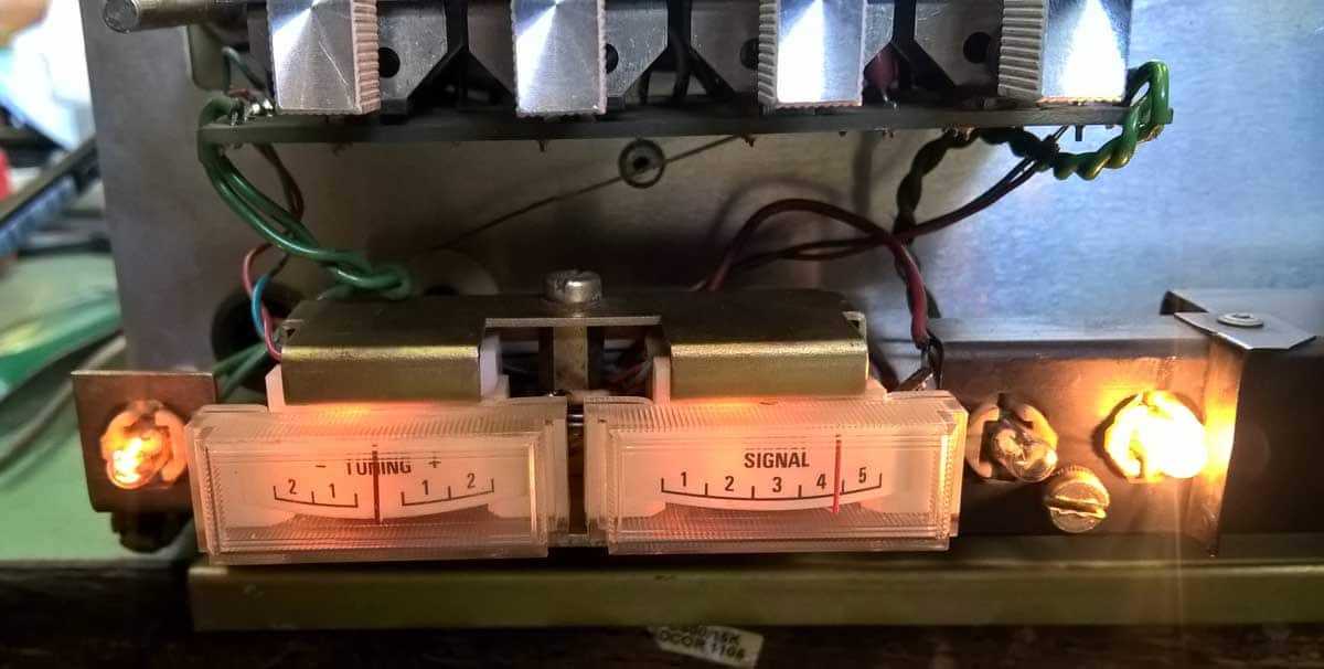
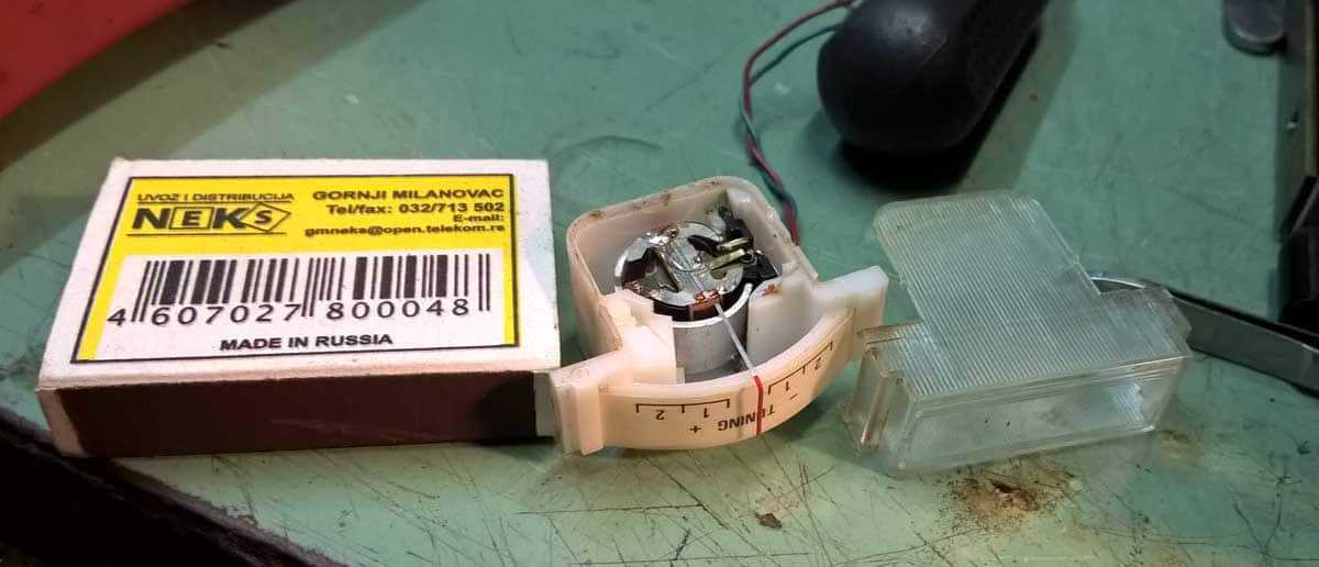
Daklem - odlemio cajger sa radnog A76 , otvorio , zamenio skalu sa Doktorovog (mala razlika u design) ....... turio ga na mesto ....... Ajd - da ponovim - tuner se besrekorno ponasa po pitanju prijema , po svim parametrima ; ali - center tuning cajger baca u levo ..... OK - ima se SM , nadjoh predmetnu sekciju , malo igranja i center cajger se ponasa .......
-
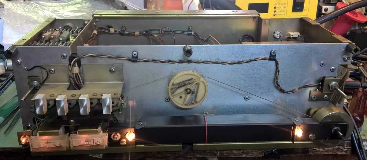
Elem , i dalje cajger ........ 3 nedelje rok isporuke ; Ajd sad - ima Doktor tuner , izdrzace on toliko ....... al' necu ja Okrenem se , skinem jedan moj A76 sa police ....... skinem front - uzecu cajger sa njega i kompletirati , a kad dodje drugi za 20-ak dana , kompletirati nazad .... Ne lezi vraze - ispostavi se da sam ihajj onomad takodje crknuti center tuning cajger na tom primerku zamenio sa odgovarajucim iz furde ....... koji em je neprovidnog kucista (pa ne moze da svekli!!) ,em je ponesto tvrdji (veca struja za puni otklon) tako da ne bi imao odgovarajucu akciju levo-desno ........... Dobro ...... idem bar da kupim kamionske sijalice (za instrument tablu) 24V/1W2 ........ one su mizerno jace od originalnih (24V/30mA) i dokazano vec rade ; a vala mnogo jeftinije nego original , pa nama triput draze ...... em odmak em dzabak Zalim ja ...... 20-ak dana ........ tu mi pogled pade na moj radni tuner (mnogo nisko na polici pa ga nisam odmah ni zamijetio )........... ihaj - ima tu jos jedan instranumenat ........ ima nade da sklopim ovaj , kad sam vec poceo Eve , slika - koju cete retko imati prilike da vidite :
-
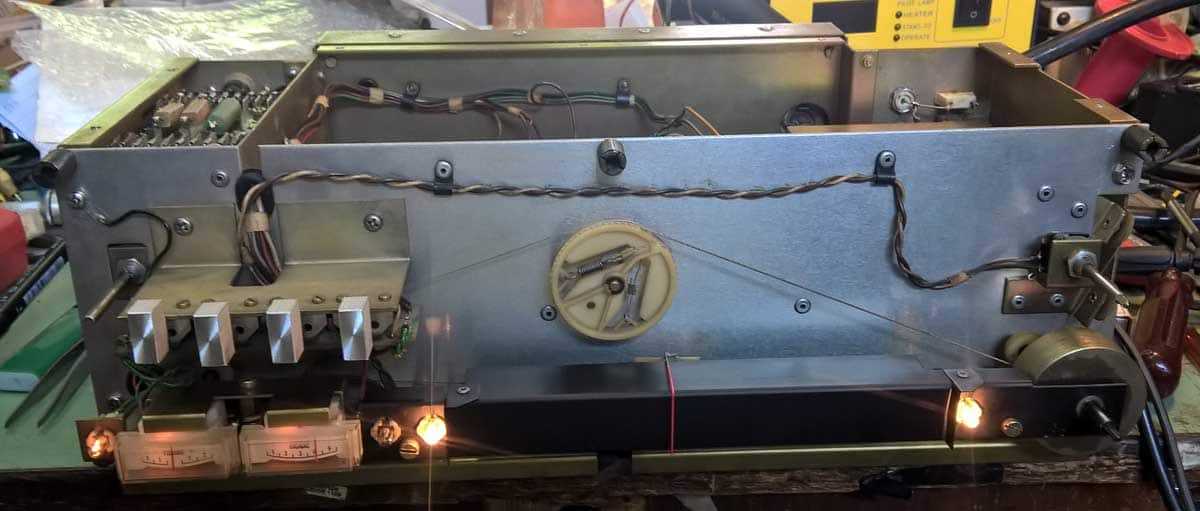
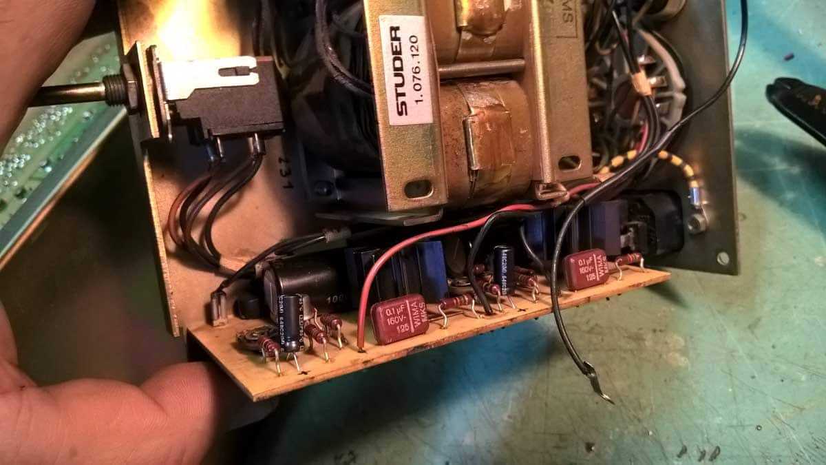
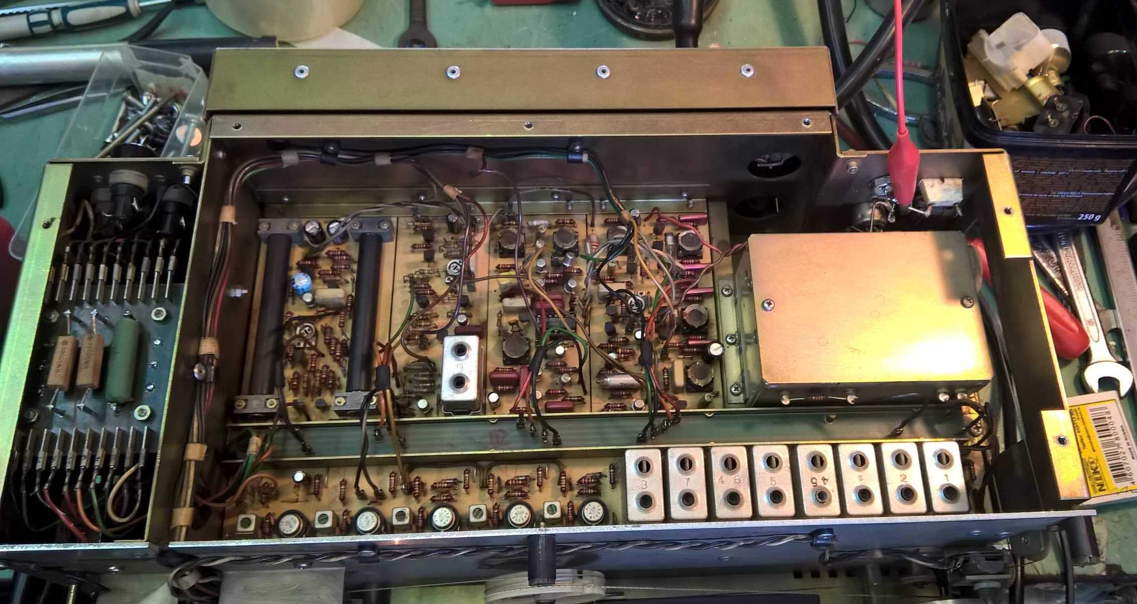
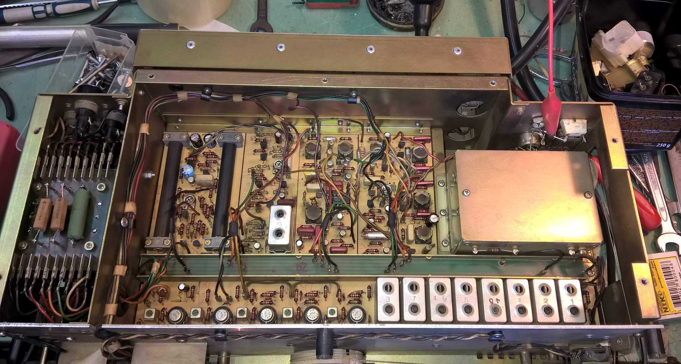
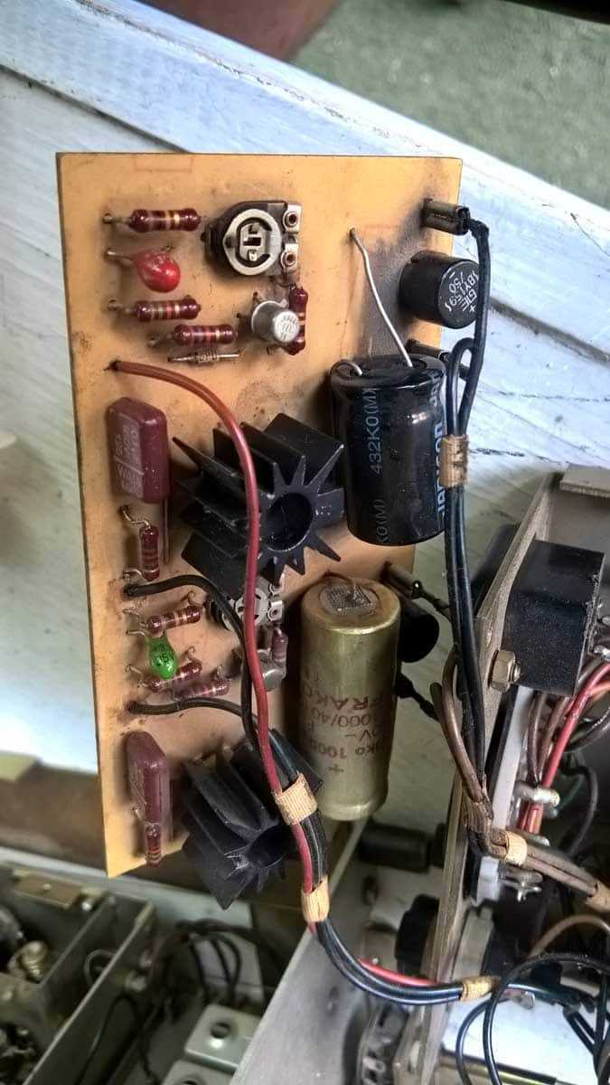
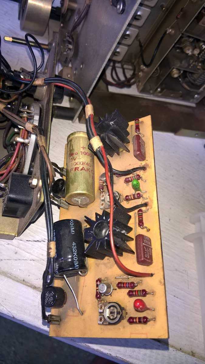
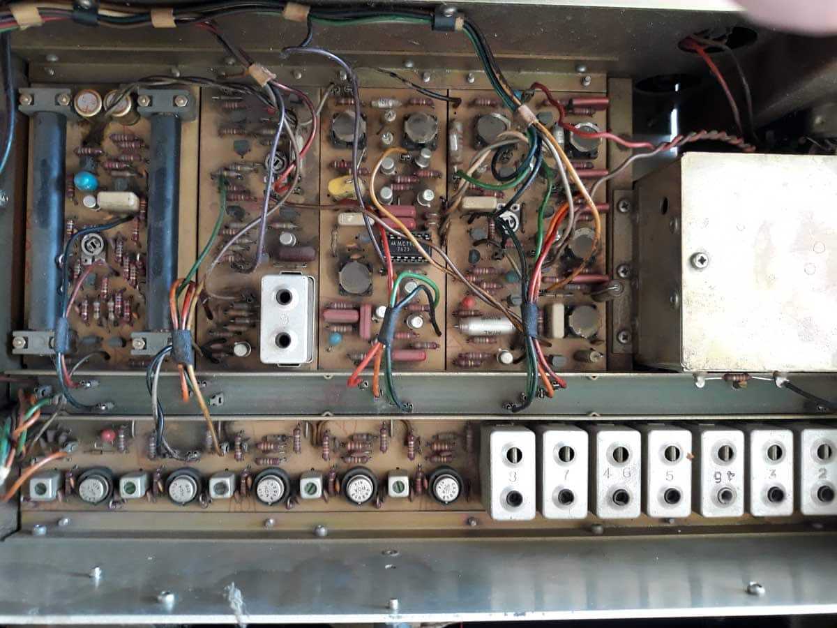
Onda se krenulo pomalo ....... Iscetkana i izduvana prasina, zamenjeni svi elektroliti , tantali zamenjeni modernim kvalitetnim elektrolitima , popravljeno napajanje, zamenjen stari ne-IEC mrezni za IEC, zamenjen BNC antenski konektor za klasican zemski (da ga i baba pozna za sta je), ispravljen prednji nosac dial dugmeta, podmazana lezisna mesta dial osovine izlazni elkovi bypassovani sa 1uF MKC , izbaceni izlazni level trimeri, zalepljen frontalni lim prednjice ........ na svakom primerku kojeg sam imao prilike da vidim - odlepio se od bazne plastike na levoj strani, krenulo se u potragu za cajgerom za center tuning ........ nema u furdi ....... Guja pomogao i locirao u Buerklin-u.
-
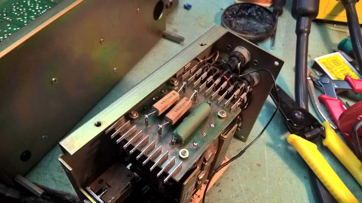
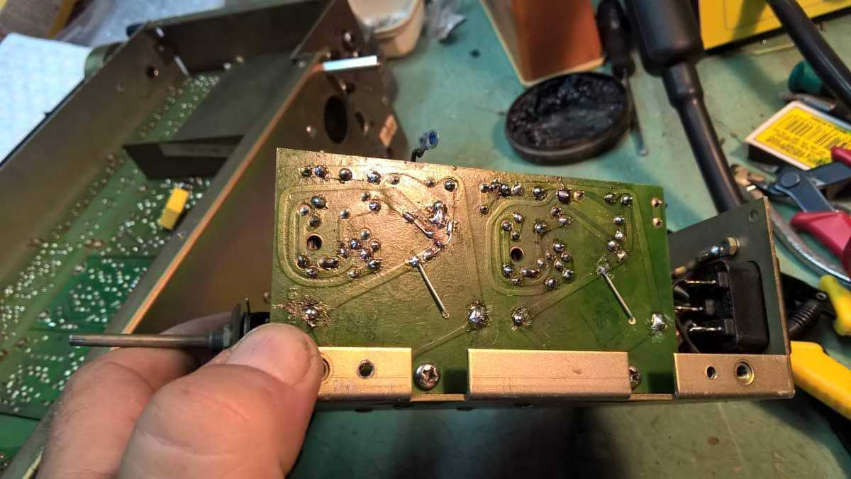
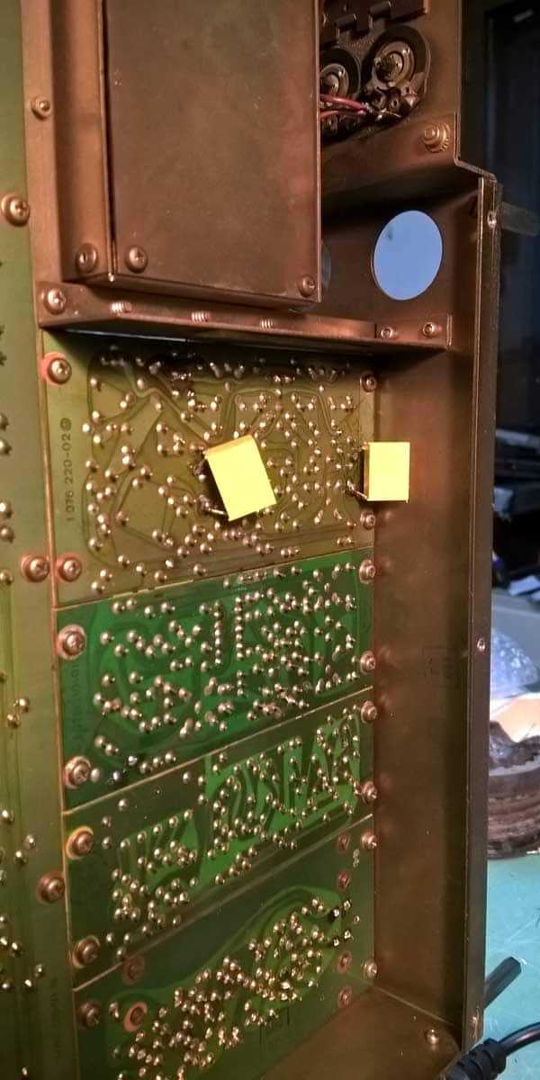
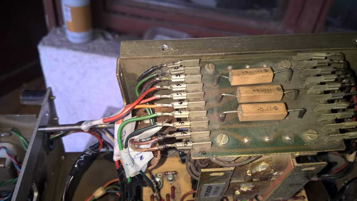
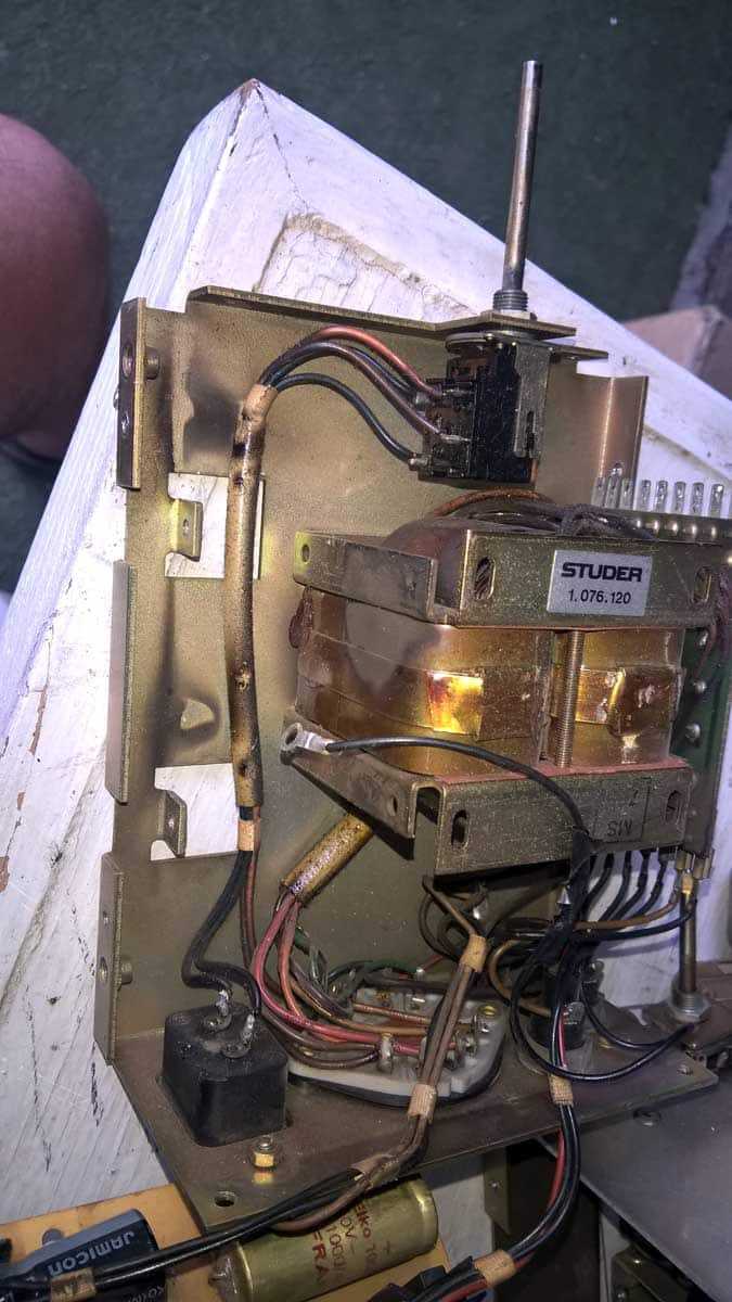
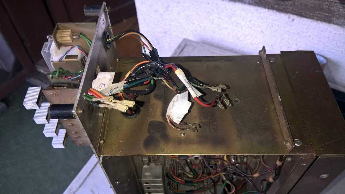
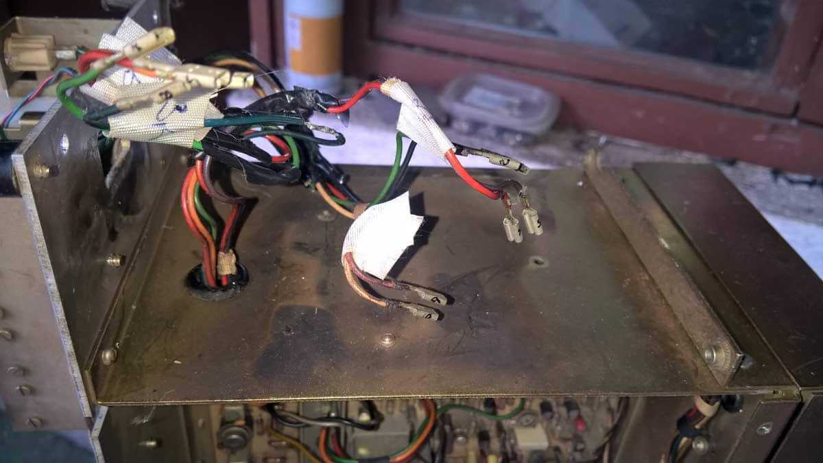
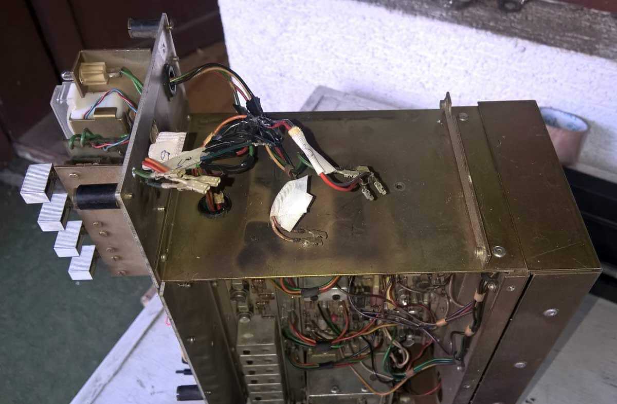
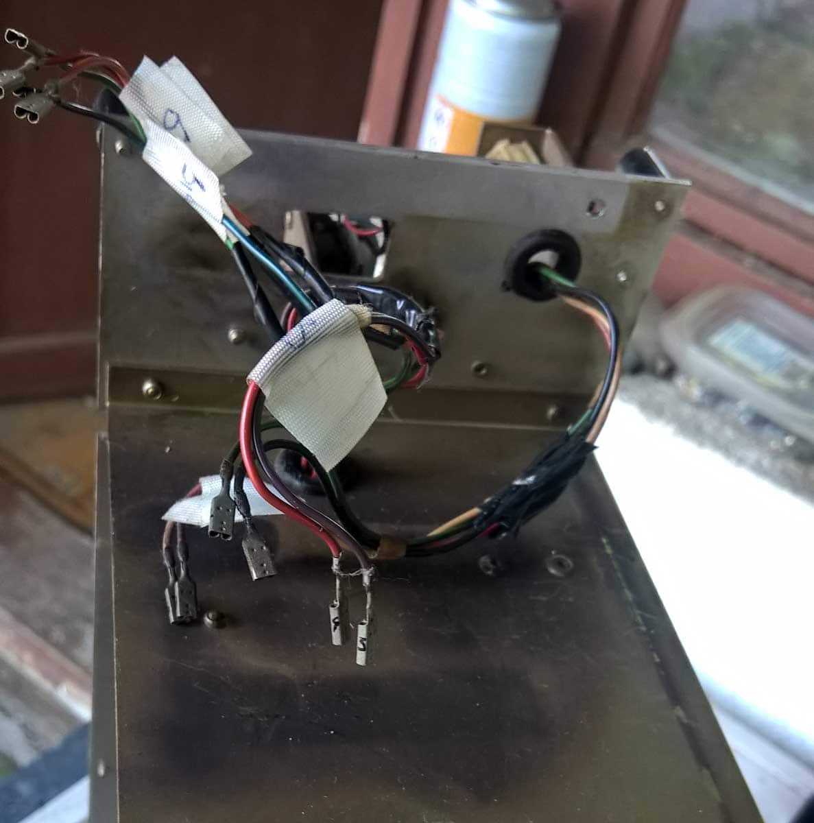
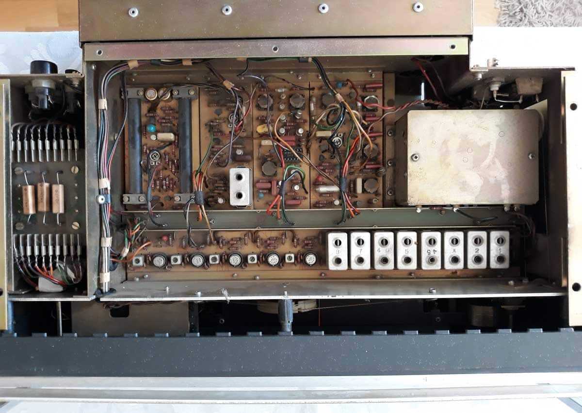
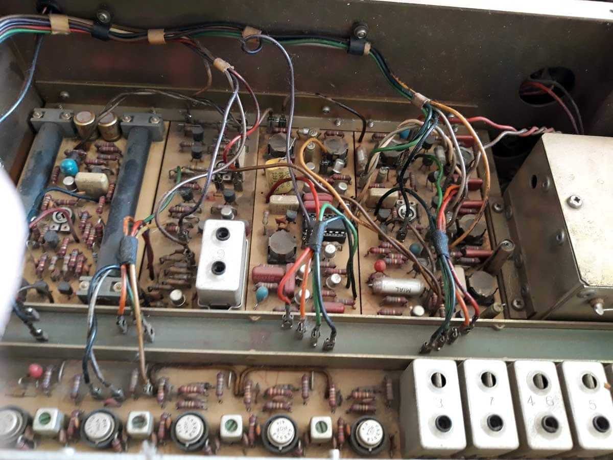
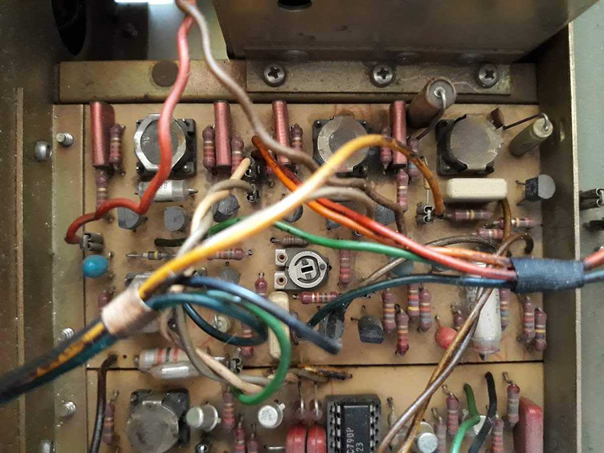
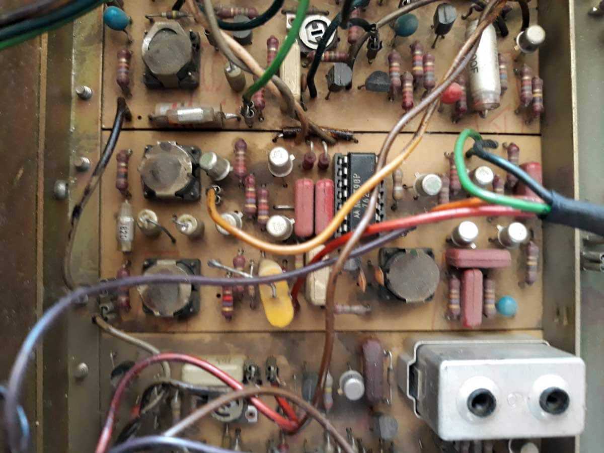
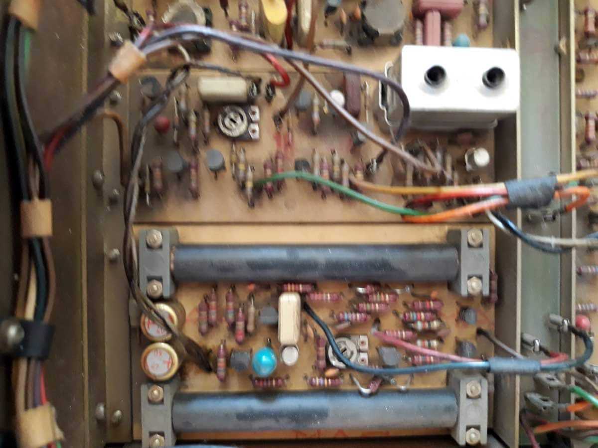
Iz prvih slika je evidentno da je neko vec pokusavao da ga popravi. Standardno crkava sekcija napajanja posle 20++ godina heavy upotrebe , te se suse elektroliti u ostatku uredjaja ...... a vala ne treba ni tantalima verovati. Srecom pa ih i nema nesto puno. Takodje odustane od rada jedan od dva instrumenta - center tuning ili signal strength Dakle - prve slike po rastavljanju (brojevi na stopicama napisani crnim CD markerom su moj lukavi trik ; valja uraditi na obe grupe stopica):
-
eve prvo slike koje je Tadijasid poslao kao info ; vidljiva je stanovita kolicina masne radijske (citaj - duvanom obogacene) prasine ....svi takvi primerci su , za moje znanje , radili kao monitoring u radio stanicama diljem negdasnje nam domovine. Iz tih slika je bilo skoro pa sigurno da niko nije cackao po prigusnicama oscilatornih kola (bilo bi valjda tragova u toj prasini) , iako imamo Goshu za pomoc ....... bolje je kad ne treba .
-
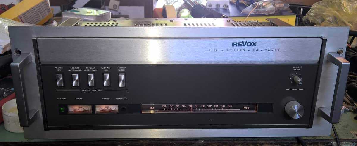
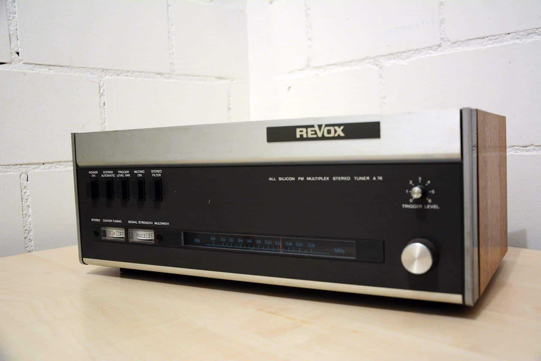
Elem , pre nekog vremena krenusmo neko domundjavanje ....... (kad se dodje u stanovite godine onda fetishizacija uzima maha kod svih nas) , Doktoru palo na pamet da nabavi neki tuner ...... Kako, zasto bas ovaj model , Doktor ako ce da doda , neka doda ...... mene mrzi mnogo piskarati Elem , sretan sticaj okolnosti da je forumski nam drugar Tadijasid preko Limoondoo stavio na prodaju svoj primerak , Doktor po nicku poznao ko je u pitanju , priupitao za fotke ispod zita i posteno izbidovao ..... Onda se posrecilo da je Tadija provozao tuner do obliznje mi BP , ja ga preuzeo i onda zapoceo ugodan mi posao. Slikica sa neta : A76 MKII , domestic iteracija ; Sad vec Doktorov primerak je broadcast iteracija - Studer ga je isporucivao u sklopu svojih paketa opreme , bez drvenog oklopa , dodajuci rack mount pribor/masku kao i dodatnu tepsiju nazad sa elektronikom za bal. izlaz.
-
ako nema Guja , ne znam ko ima
-
rekoh ti bc639/40 imas u svakoj trafici
-
kad ti je sve blizu
-
zadnja slika na bayu su dimenzije prvo kod Gujomira , onda bay ako zatreba kad stignem do radionice , sve dileme resene
-
ce te zovem later gujetino jedna , mogo si oma da kazes
-
ja sam pravio otvore na donjoj ploci - ubacivao mrezu , dok su bocni otvori bili perforirani to donekle popravi situaciju google za henessy musical fidelity A1 , imas recept kako da se resis bednog preamp stage-a , dobices duplo bolji amp , kojem usput nece prokrcati pot posle 6 meseci po zameni promeniti sve elektrolite , obnoviti pastu i na tranzsitorima i na sklopu hladnjaka obavezno obnoviti lemna mesta gde god se vidi da je lemna tacka umorna od grejanja pozeljno staviti metalni graetz umesto dioda , originalne su odavno prekuvane onda mu obezbediti vazduha , mozda cak i 12cm ventilator u polici da duva sa boka (na 5-7V se i ne cuje) i sluzice mnogaja ljeta
-
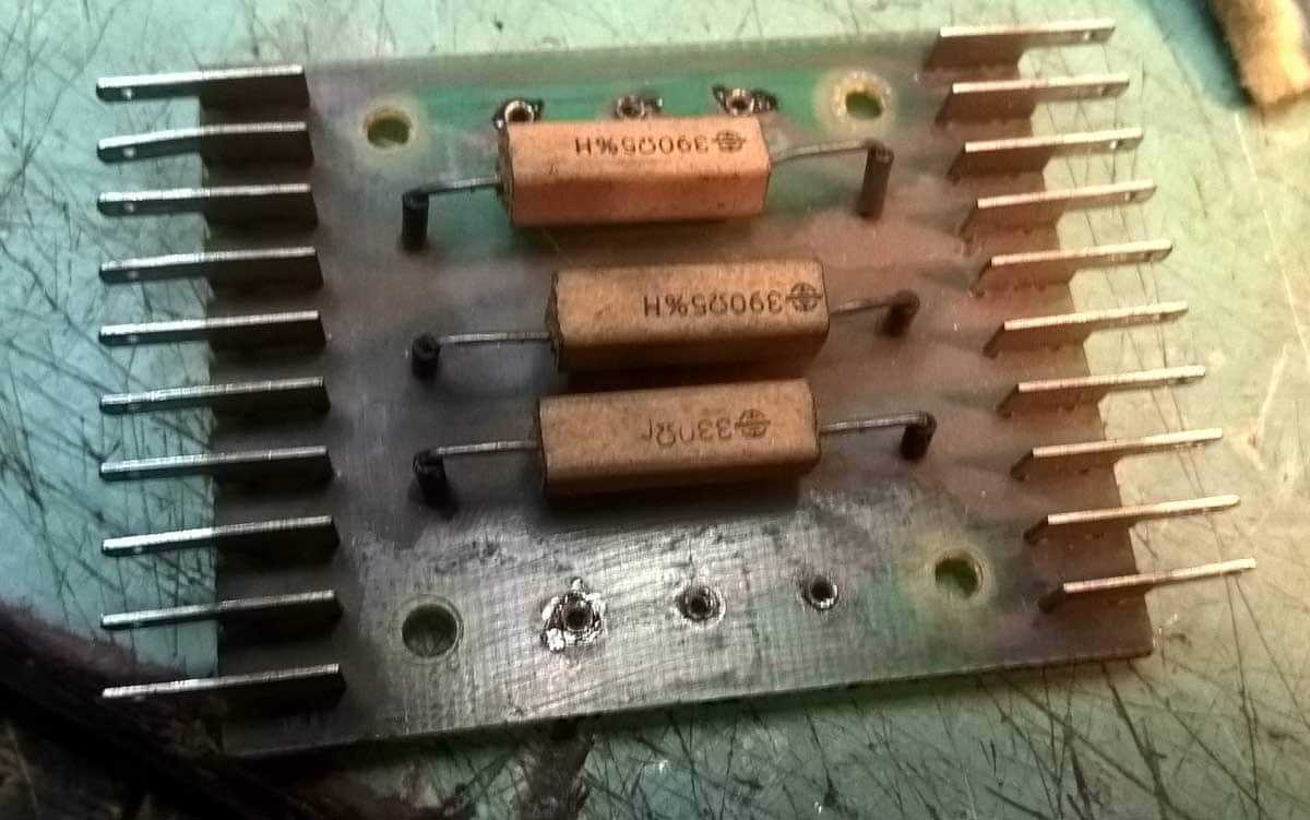
imate vi nesto korisno da dodate ? cajger recimo ? edit: nixie ipak koristan , ovo odgovara 99 posto , ako nista ono bar za donora tnx
-
jedino da rasturam ispravan A76 da izmerim kalem , al' jok a 50 ojra bih dao za to u loodiloo ma pasace bilo koji genericki instrument , samo da je miran polozaj u sredini cu sutra poludim i probam normalac da prepravim u centralni
-
potreban odgovarajuci instranumenat , komada 1 ako imate nesto slicno u furdi , da vidimo .....
-
contact Store i resice ti
-
-
dobro , znam - imas opravdanje - udarili silni partikli u glavu , pa si se malo odmakao od svakodnevne praxe oprosteno ........
-
tol'ke godine po laboratorijama , a pojma nemas redosled je ovaj : 1.tocak 2.leptir staklo 3.e-book reader 4.signalni transformator , u izvornom obliku telephone repeater onda 100 praznih mesta , pa sve ostalo
-
ja ako kazem da je kinesko , onda je kinesko kako sam danas Woliju buseo rupe sa kineskim burgejama mada ona najveca je isla sa ruskom
-
kineska supa s noodli je zakon


-
Trenutno na sajtu 0 članova, 0 Skrivenih, 128 Gosta (Pogledaj celu listu)
- There are no registered users currently online
-
Forumska statistika
9.2k
Ukupan broj tema451.9k
Ukupan broj objava -
Statistika članovȃ
3012
Svi članovi5071
Najviše na sajtu