


neskor
-
Broj sadržaja
2861 -
Na DiyAudio.rs od
-
Poslednja poseta
-
Broj dana (pobeda)
34
Content Type
Profiles
Forum
Blog
Kalendar
Sve objavljeno od neskor
-
svako ulje ili lak ima da malo pozuti drvo gledam da to izbegnem ali izgleda da je to nemoguca misija
-
jedino mi ostaje kako da uradim finish koliko sam skontao ne postoji nacin da ostane ova boja drveta ako ga budem mazao necim, a meni se bas svidja ovako mozda da uradim gornji i donji sloj od crnog plexia ili da celog furniram u neki americki orah
-
bice nesto

-
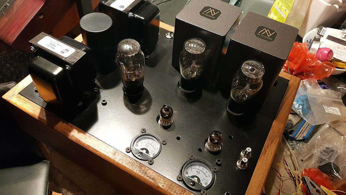
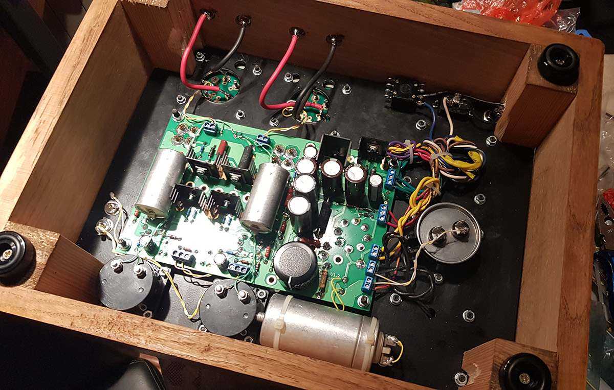
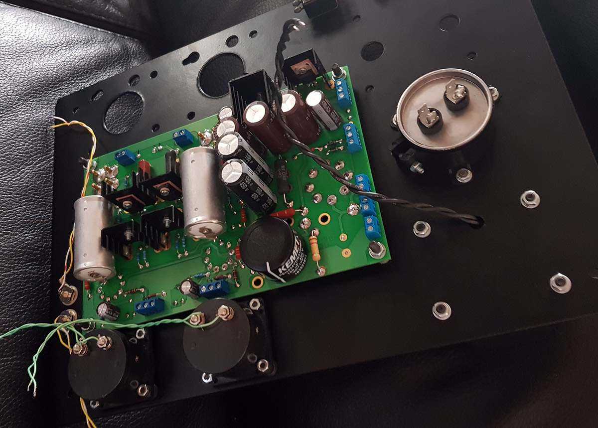
izlazni trafoi su fabricki NP acoustic http://npacoustic.com/en/
-
amp je jos u testnoj fazi, tako da u sledecem koraku cu onda uvodnike ubaciti, poskidati redne kleme i zalemiti sve kablove direktno na plocu
-
Rupa je bila velika, kabl nije nategnut, a i ploca plstificirana tako da nisam o tome razmisljao, ali ima smisla.
-
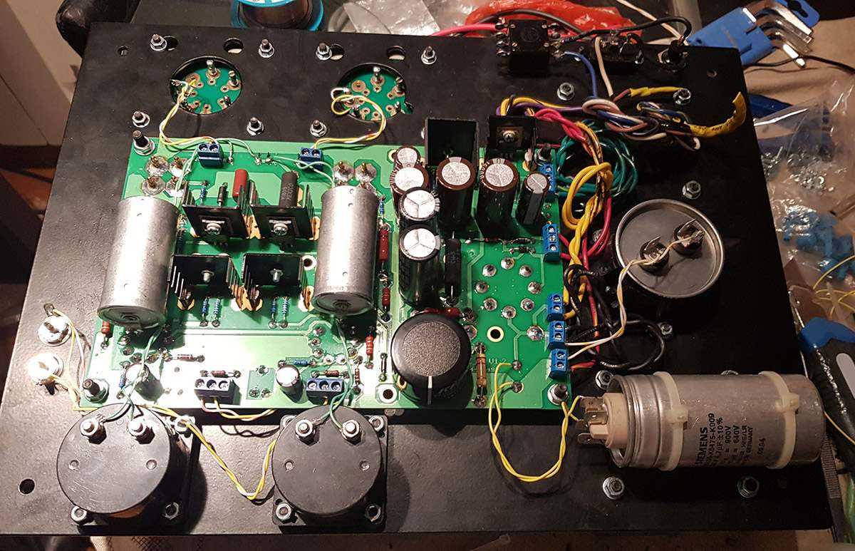
danas slusanje sinoc sam zavrsio amp oko 23h, tako da nisam imao vremena za slusanje, na srecu komsija :))
-
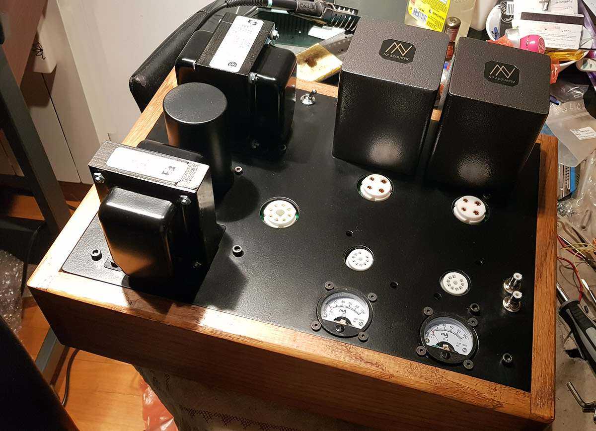
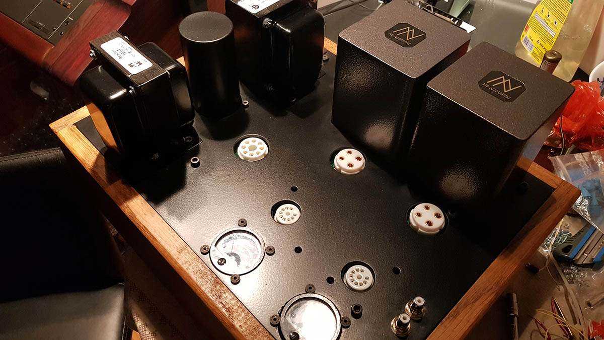
i na kraju gotovo pojacalo
-
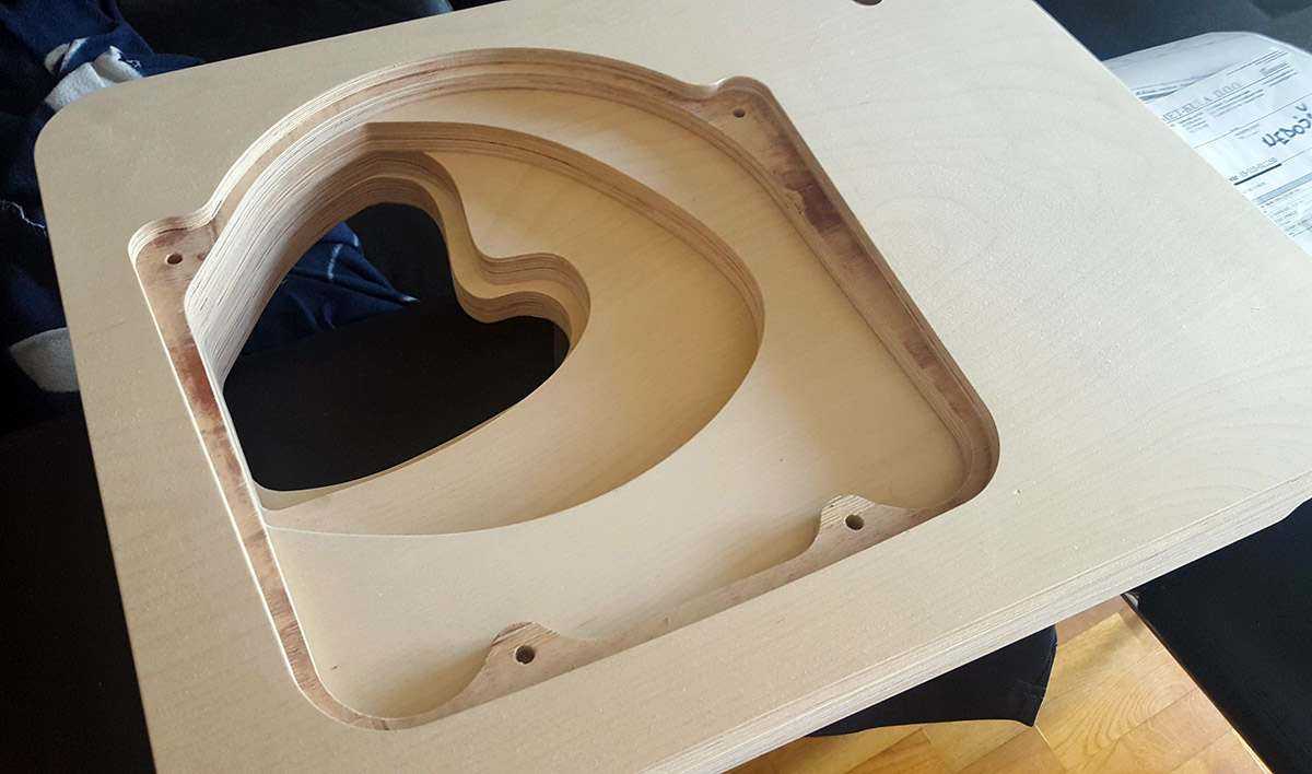
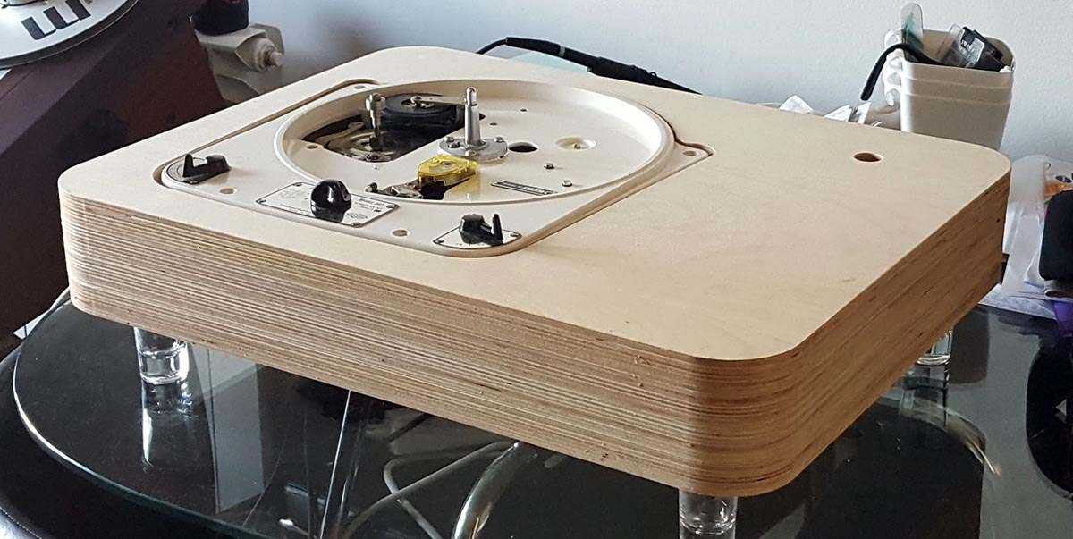
i onda drvena kutija
-
zatim ubaceni delovi
-
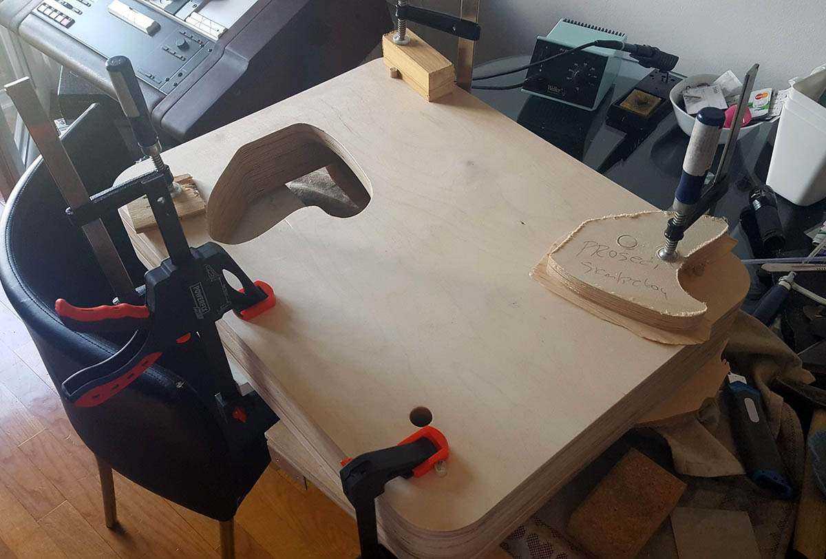
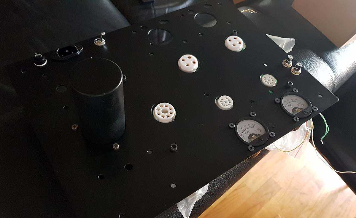
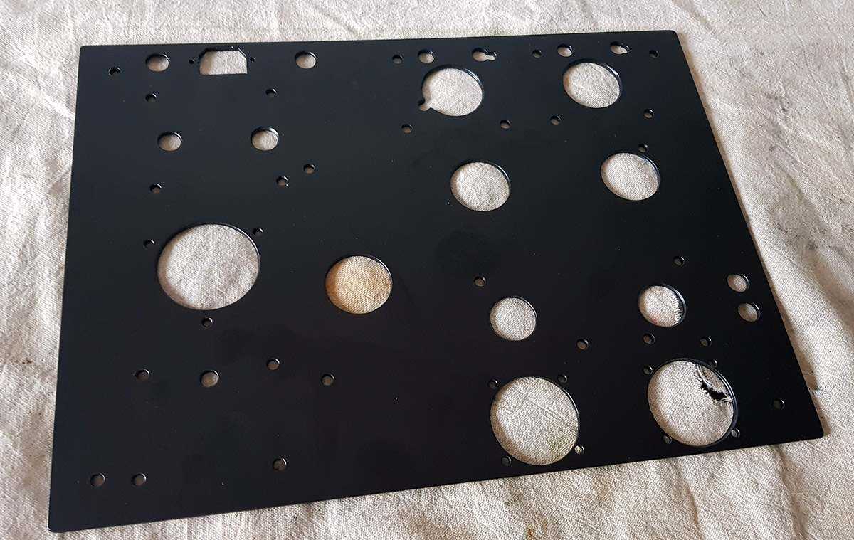
konacno uhvatio malo vremena da skutijam ovaj amp gornja ploca izbusena i plastificirana
-
ovo se retko vidja na oglasima Western Electric Horn 16a, Amplifire WE46c 2pc Preis: 140.000 € VB https://www.ebay-kleinanzeigen.de/s-anzeige/western-electric-horn-16a-amplifire-we46c-2pc/1156947217-172-6187
-
Ken Shindo Garrard Hammertone 301 Turntable, Mersault RF-773 tonearm https://www.ebay.com/itm/233280101044 cijena prava sitnica
-
samo za magacionera JBL DD 55000 https://www.ebay.de/itm/JBL-DD-55000/123825569237?hash=item1cd4943dd5:g:~ksAAOSwuVFdH3k5
-
ja koristim isto 5963 umesto ecc82 po meni zvuci bolje od svih ecc82 sto sam imao
-

Zanimljivi & smešni na You Tube
neskor je odgovorio/la Leonardo's temus u Muzika , Film i Fotografija
-
meni vise ni ne treba sa 45 mogu izvuci max 2W
-
sirina je 4cm, a debljina stuba je 1.5cm, duzina 8cm
-
C jezgra su oko 8X4 cm te kondove sam satavio dok su Tamure vec bile prikljucene
-
vrlo rado, da imam mesta u sobi za kutiju od 200-300L
-
pa nisi bas dobro izracunao navedena cena je za par mene je izaslo Product Amount Shipping Cost Total Amount US $ 40.98 US $ 25.16 US $ 66.14 za te pare tesko da mozes iole da napravis nesto da je na tom jezgru
-
https://www.aliexpress.com/item/Double-C-amorphous-core-5K-single-ended-output-transformer-for-300-600-ohm-headphone-front-output/33025063931.html?spm=a2g0s.9042311.0.0.25b04c4drHl2lS nije imao u ponudi ove moje, pa sam ga pitao i covek mi napravio verovatno mogu da naprave bilo koju kombinaciju koja ti odgovara
-
i Altec coax
-
prvo sam probao kineske, i zvuk je malo bio muljav, pa sam prikljucio Tamure i to je bolje zvucalo u medjuvremenu ubacen motor run kond kao zadnji kond u napajanju, kao i mali PIO kao prvi, odmah posle GZ32 slusao tako neko vreme, pa sam zatim opet ubacio kineske i sada mi kineski zvuce mnogo bolje, tako da ostaju za sada tu u nego dogledno vreme probacu jos koje izlazne trafoe i na kraju da sve to polako stavim u kutiju
-
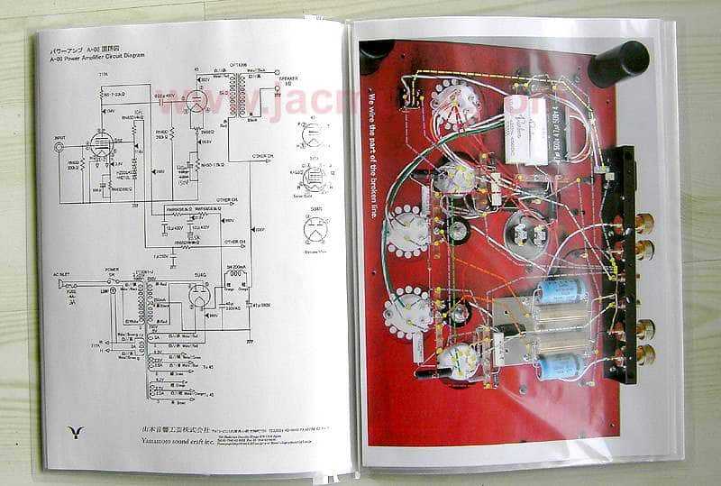
pa i nije bas Yamamoto ima vise slicnosti sa mojim prethodnim projektom C3m/300B Tu je pentoda kao driver Evo i seme za Yamamoto


-
Trenutno na sajtu 6 članova, 1 Skrivenih, 110 Gosta (Pogledaj celu listu)
-
Forumska statistika
9.2k
Ukupan broj tema452.2k
Ukupan broj objava -
Statistika članovȃ
3017
Svi članovi5071
Najviše na sajtu