


neskor
-
Broj sadržaja
2861 -
Na DiyAudio.rs od
-
Poslednja poseta
-
Broj dana (pobeda)
34
Content Type
Profiles
Forum
Blog
Kalendar
Sve objavljeno od neskor
-
Ako ide Buc Kesidi onda mora i ovo
-
kada smo kod domace muzike, ovo mi je super obrada Bajagine pesme
-
Fs od 48Hz je po meni malo veci problem (ako se ide bez suba)
-
imas kod brace madjara, dve za 24 EUR+shipping https://www.ebay.de/itm/2x-ECC81-12AT7-Telefunken-Rohre-tube-tested-same-code-TOP/333182458171?hash=item4d9338d93b:g:qXgAAOSwjCVczXNU
-
video sam to pisanje jos ranije svaki savet ili misljenje je dobrodoslo
-
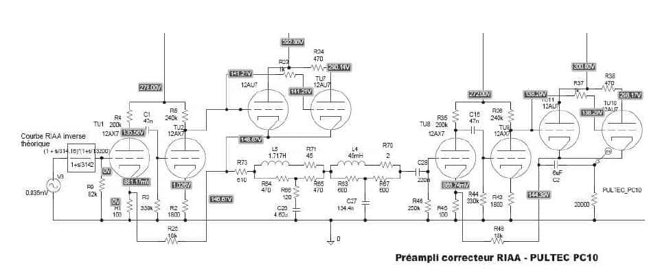
Evo i analize cele sheme Originalni tekst je na franscuskom, tako da je provucen kroz google translate The RIAA Pulltech PC 10 RIAA Corrector The RIAA correction preamplifier Pulltech is without doubt, with the amplifier Ampex , one of the projects that mobilized the largest number of participants. It is invested MM. Preyal , Goewie , Cocheteux , and perhaps others I forget, forgive me ... But let's start with an excerpt from Rinaldo Bassi's article in NRDS No. 221 where our dear "paleo Electronologist "has dissected the Pulltec scheme. The input transformer This is the famous K241D from Peerless (a division of Altec ) Forgive us for the little, but this universal transformer accepts impedances of 31.5 depending on the commutations; 37.5; 125; 150; 280; 340; 500 or 600 Wat choice in symmetrical or asymmetrical. The bandwidth at +/- 1 dB is 10 to 30 000Hz. It can operate at voltages as low as 0.5mV and up to 30V! And this without background noise, thanks to a balanced primary winding and coupled with the secondary. The snoring is in phase opposition while the> is 10 to 30 000Hz. It can operate at voltages as low as 0.5mV and up to 30V! And this without background noise, thanks to a balanced primary winding and coupled with the secondary. The snoring is in phase opposition while the signal is in phase. A superb shield offers an efficiency of 90dB. What to dream our audiophiles in search of a cell transformer with voice coil. For'EMT TSD 15, the 37.5 W transformer position is the right one. The secondary is in this case loaded by a resistance of 82 k W ( see diagram ). For a Denon DL 103 it is a load of 125 W the secondary will be charged by resistance of 70 k W If you build the device it is necessary to use a standardized load of 47 k W at the input for mobile magnet cell. For variable reluctance cells, use your usual adapter transformer or pre-preamplifier if you are satisfied with their performance. The first stage Two modest tubes: a 12AX7 and a 12AU7. Yes! it's stupid, but it works. Between brackets, the second stage is virtually identical to the first. The entrance stage looks stupid, but it hides a hint! We enter on the grid of V1 we leave on the plate loaded by 200k W Until then it is normal. A modest 0.05μF capacitor provides the link on the V2 gate (which is more than enough, the attenuation being less than 3dB at 10Hz for a gate leak resistance of 330k W. The amplified signal is recovered on the resistor. load 240k W . the tube is biased at -1V by the cathode resistor of 1800 Wnot decoupled. This is where the trick begins. The connection is direct between the V2 anode and the V3 grid (12AU7). We then find two 12AU7 in parallel, the second being damped by a resistance of 480 W in its plate circuit, which will act on the slope of this tube second tube, and therefore on the overall slope of the two tubes in parallel. We will see later why. In the cathode of the combined tube, there is a resistance of 18k W series with a resistance of 200 W placed in the cathode of V1. The quiescent current that passes through these two resistors will ensure the polarization of V1 (-1.4V) and of course V3 V4 (120V, which provides a bias of -8V on the grid through the direct link). This original montage has several purposes. First of all, by the play of the quiescent currents, a virtually constant gain is ensured throughout the lifetime of the tubes, since the polarization point of the first 12AX7 was not chosen at random. The figure below shows that with 135V on the plate of a 12AX7 and a polarization of -1.5V, we are on a point where the slope, the internal resistance, and therefore the amplification coefficient of the tube are variables. Any drop in tube efficiency input is reflected in the polarization of the output tubes, thanks to the direct connection, the current increases in the 12AU7, thus reducing the polarization of the input tube to a correct value. This is very important for the future, because we must now look at dynamic operation. If you carefully examine the circuit, you will find that looping V3 V4 on the 200W resistor in the cathode of V1, will cause a very particular phenomenon. Against feedback? No it's a reaction. On the Schematic we have indicated a series of + and - corresponding to the positive alternation of a periodic signal. We could have chosen the negative alternation, it would be enough in this case to replace the + by - and vice versa. What will be the effect of this reaction? Given the chosen polarization point (-1.4V), the gate swing will cause slope variations of V1, therefore the amplification coefficient. We will have created a real expander of dynamics ... This is the secret Pulltech. This is the same type of circuit used by Audio Research at the output of the famous SP10. Nothing prevents a manufacturer to tackle this type of circuit very difficult to develop: The rate of feedback must be calculated. quarter-hair "because we risk creating a perfect oscillator if the circuit is poorly controlled, which is not the goal! Cathodes in parallel with the 12AU7, we will then attack the passive filter of the RIAA correction.Before going further, we must talk about the filter. The RLC filter RIAA Ideally, a passive RLC filter that must follow perfectly the disk etch correction curve must be constituted in the following way: A resistor and a parallel capacitor having a time constant of 75 μs which corresponds to a frequency of 2120 Hz (-3 dB). Why 75μs? Simply by that it is the standard of deemphasis in frequency modulation adopted by the USA since 1939 (50μs in Europe). A resistor and a series capacitor having a time constant of 318 μs (frequencies 500.4872 Hz to -3 dB). An inductor and a parallel resistor having a time constant of 3180 μs (frequency 50.04972 Hz at -3 dB) RIAA correction is the algebraic sum of these three curves transmission.C'est the standard filter used by PullTech and reproduced by Tango (EQ600) These filters have an input and output impedance of 600 W .It standard and it is the ideal compromise for a reasonable Q of the filter coils whose resistance rarely exceeds 60 W. However, the good functioning of a filter depends essentially on what is called the image of the impedance of the entrance to the exit and vice versa. Two solutions are possible as we will see: The input and output impedance of the filter is equal to the impedance of the filter itself. In our case, the source and the load should be 600 W . The circuit recommended by Tango consists in isolating the filter between two impedance transformers 600 W each. Heavy and impractical solution although used in some cases. The impedance of the source at the input of the filter should ideally be zero or at least ten times lower than the impedance of the filter itself provided that it is strictly constant throughout the transmission curve of the filter. On the other hand, the load impedance of the filter must be infinitely large or, for lack of better, at least ten times greater than the output impedance of the filter. It is this very difficult solution to be developed which has been adopted by Pulltech thanks to its "magic" circuit. Pulltec : an ideal impedance adapter This is the third advantage of the Pulltec circuit. By the play of the reaction that we analyzed in the preceding paragraph and the resistance of 480 W placed in series in the anode of the second half of the 12AX7, we will act on the slope of the new tube thus combined by the two half in parallel the output impedance of the circuit is 50 W and remains rigorously constant throughout the useful spectrum. The filter can be attacked without disturbing the output of the filter, Pulltec offers the luxury of building a corrector also has a constant impedance and is approximately 50k Wthat is almost 80 times the filter output impedance, regardless of the position of the knobs. This ultra-fine adjustment will allow to correct the bandwidth accidents of certain cells in the high-end spectrum, and to boost or attenuate the very low frequencies (practice to eliminate the rumble). In the middle position, the transmission is rigorously straight. The output stage It has the same structure as the input stage with the exception of the reaction rate which is less important (cathode resistance of 100 W instead of 200 W in the input stage). The output is effected by the cathode of 12AU7 on a output transformer ( Peerless or Triad depending on model) ensuring the normalized symmetric transmission 600 W . If you build the device and you want to do without the transformer, remember to replace it with a resistance of 20k W so that the circuit retains all its dynamic and distortion characteristics asymmetric.
-
evo ako se neko odluci da pravi Pultec PC-10 RIAA lik je sve istestirao i resio problem ubacivanja Tango LCR modula u postojecu shemu etude PULTEC PC-10 28-11-2008.pdf
-
samo mala napomena, ako neko bude hteo da pravi Pultec sa LCR RIAA mora da obrati paznju na ulazni kondezator ispred RIAA filtera po semi je on 2uF, sto je premalo za LCR resenje je izbaciti taj kond i postaviti kond od npr. 220nF posle LCR RIAA umesto tog konda od 2uF staviti otpornik od 600R , na taj nacin dobijamo idealnu RIAA krivu

-
koliko znam Pultec nikada nije imao LCR RIAA vec klasicnu RC
-
update lik je ubacio jos pedesetak strana slika sa sajma
-
kao i obicno vladd nista konkretno da se ne bi zavrsila svaka rasprava sa uopstenim floskulama i teorijama zavere , ovde ima zanimljivih stvari za citanje, koga zanima http://www.intactaudio.com/forum/viewtopic.php?t=219&postdays=0&postorder=asc&start=0 http://www.intactaudio.com/forum/viewtopic.php?t=551&postdays=0&postorder=asc&start=30
-
onda sam ja nesto permutovao, posto znam da su radili 10K LCR
-
koliko se secam, to je za 10K LCR RIAA
-
da li imas neki konkretan predlog ili konkretnu zamerku, ne ovako uopsteno
-
skoro sam nabavio par Tango LCR RIAA posto vec imam Shishido sa Solaja LCR elemntima, mislio sam da napravim neku novu LCR RIAA prva i najlaksa opcija je Thostenova LCR RIAA ili ici na malo komplikovaniju/bolju? verziju ili ako neko ima neki drugi predlog ili sugestiju
-
ko ti je tu nebulozu rekao, molim te
-
Sluacajno naletih na ovaj post na FB. Covek napravio Paragon u svojoj reziji. Koliko vidim radi sa Acom Ribonom. https://www.facebook.com/photo.php?fbid=2779437762082933&set=pcb.2334554176827636&type=3&ifg=1&__tn__=HH-R&eid=ARDiFHoKNQ4P_JAm-4suQdWadsrr1iwXXBbRSIFeeZKJaLbci99BGqBpyDJ9TL5dA5GjscvK9jicABfG
-
-
mislim da sam bas te zvao pre deset godina i mogu da rade samo manje magnete
-
Ova prica traje vec deset godina. Koliko ja znam nismo uspeli da pronadjemo nikog ko ima. Bilo je prica da je bila masinu u bivsoj EI u Bataji, pa cak i u Svrljigu., ali na tome se samo zavrsilo. Koliko se secam, nasao sam firmu koja ima magnetizator ali moze da radi magnetizaciju samo malih magneta.
-
Pre nekih mesec dana sam uzeo par 15" TAD 1601a bas drajvera. Membrane su bile u dosta losem stanju, pa sam odlucio da kupim nove recone za njih. Skinute stare membrane, ociscene su i spremljene korpe za recone. Od magacionera sam pozajmio Gauss metar i izmerio magnetni flux u procepu. Izmerena vrednost je bila 10500 Gaussa, a po specifikaciji proizvodjaca trebalo bi da bude 11800 Gausa. Danas sam stavio privremeno novi recone i izmerio TS parametre za LIMP-om i dobio ove vrednosti: Fs = 28.95 Hz Re = 6.00 ohms[dc] Le = 466.05 uH L2 = 483.95 uH R2 = 11.93 ohms Qt = 0.37 Qes = 0.38 Qms = 7.91 Mms = 108.26 grams Rms = 2.574594 kg/s Cms = 0.000282 m/N Vas = 307.40 liters Sd= 881.41 cm^2 Bl = 17.705498 Tm ETA = 1.89 % Lp(2.83V/1m) = 96.11 dB A ovo su fabricki TS parametri: Theile-Small Parameters TL-1601a Fs - 28 Hz Re - 7 Ohm Levc - 1,6 Qts - 0,34 Qes - 0,36 Qms - 6,8 Mms - 116 g Cms - (x 10-4 m/N) 2785 Vas - 307 liter sd - 0,0881 Sq M BL - 19,5 no - 1,82 % Mmd - 85 g Xmax -8,0 mm Pmax -300 Watt Vd (cm²) 705 Max. Excursion Before Damage (P-P) 36,0 mm Sound Pressure Level 97 dB/W (1m) Koliko vidim parametri ne beze nesto mnogo od fabrickih. BL parametar u principu pokazuje stanje magneta. Moje je sada pitanje da li se zezati i slati drajvere preko na remagnetizaciju?
-
evo ovde mozes da turis tvoje Tango LCR module a i nije tesko za napraviti Shishido LCR Phono.bmp
-

Zanimljive, smešne i čudne fotografije
neskor je odgovorio/la Mikorist's temus u Muzika , Film i Fotografija
ili ti "Mijatovićeva prečka"Ulje na platnu. -
Zanimljive, smešne i čudne fotografije
neskor je odgovorio/la Mikorist's temus u Muzika , Film i Fotografija


-
Trenutno na sajtu 6 članova, 1 Skrivenih, 110 Gosta (Pogledaj celu listu)
-
Forumska statistika
9.2k
Ukupan broj tema452.2k
Ukupan broj objava -
Statistika članovȃ
3017
Svi članovi5071
Najviše na sajtu