


Zen Mod
-
Broj sadržaja
40228 -
Na DiyAudio.rs od
-
Broj dana (pobeda)
594
Content Type
Profiles
Forum
Blog
Kalendar
Sve objavljeno od Zen Mod
-
ih, sto si stipsa
-
osnovno je bez zurbe i onda ide bez problema kirner, zabusivac, podmazivanje stepenaste burgije pod obavezno spiralna moze samo ako je masinsko busenje, gde je predmet obrade stegnut idi begaj mda, lepotinja ploce se uvek buse sa nalicja za zastitu - molerska papirna traka je zakon
-
oblik surrounda je daleko manje bitan od vrste i kvaliteta istog, u kontextu uloge vesanja da treba da provede poduzne talase do korpe, samim time da spreci refleksije istih u membrani generalno mrsomud; dobar zvucnik se pravi tako sto uzmes i napravis msm, ja to ne znam, mali sam jos za to ....... a kako ide, necu ni porasti
-
-
dnevni boravak u Neletovom Guest House bole njega, bole goste zvucnjaci razmena poklona sa Sony-jem (on im poklonio Sony VFet Commemorative amps), a ostalo isto tako - pokupljeni viskovi super za cooliranje sa vinilom
-
meni nesto vilica nije pala
-
pa sad, tesko ce da ti kaze pa da ti prenese tacno sto je mislio , mislim da ti razumes sta je on mislio znas i sam da takve stvari ne idu bez tehnickog crteza i ostale dokumentacije zadnjih deceniju dve , stvari u mnogome olaksavaju programi za simulaciju magnetnog kola naravno, papak kao ja - i da naucim nesto oko programa - sta ce to meni kad nemam pojma o magnetima niti imam ideju sta bih radio sa tim coveku koji vec ima znanje o problematici , taj program dodje super alat ukratko - tesko ce imas koristi od opisa kao i uvek - definisani projektni zadatak u mnogome olaksava dalji rad .......... primer - za jednu vrstu zvucnika ultratesan procep je pozeljan i koristan, za drugu vrstu zvucnika nije cak ni pozeljan dakle - drzi se konkretnog primerka i trazi savete za njega, da se ne pogubis u informacijama
-
perfektan primerak da se momcovi uce jos kad im das po koji detalj, ihaj, kud ces veceg zadovoljstva od nauke ene, smejala se fukara onomad kad sam ja tretirao Tannoy surround sa lepkom za pacove psi laju, karavane uče nešto novo svaki dan
-
krutost
-
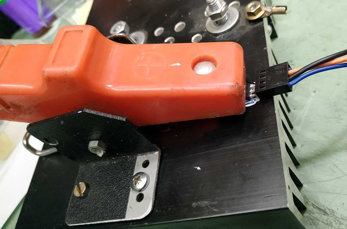
ne vidim , ali mislim da ti treba lock mehanizam - ono - dva šrafa za dva stubića
-
550/72/B su dobro radili u Cheap Trick 142
-
naci ce se nesto, kome treba a ima ih u hungarijama, garant
-
premazi obadva jednu ruku sa gornje i jednu ruku sa donje strane membrane
-
i dalje superb kandidat za izvanredan Gyurgyevak
-
ako je namazana necim da je treba "odmascivati", nema vajde ni odmascivati ni damarovati daj krupne slike oba komada, da se vidi membrana ljudski
-
90Hz-10KHz
-
pricamo o impregnaciji konusa basa, jer je originalno nekako suvkast tu ce ti Dammar odradi, ostalo ne kontam sto pomijnjes sem iz zaebanciju
-
es normalan .......
-
koristi sta imas
-
24h izmedju dve ruke najbolje potrazi Kohinor - tamno braon bocica
-
Boucherot - neko tako zove RC clan u paralelu sa driverom, koji vrsi kompenzaciju porasta induktivnost drivera prepoznaces to sto ti rekoh jeste pravljeno nekad , uz merenja na peske nacin pre PC-ja, radilo se sa onim sto se imalo u radiju, a imalo se
-
-
memrane premazi sa dve ruke dammar-a, s tim sto deo ispod kalote mazes odozdo, sa zadnje strane membrane izvodnica visokog - prakticno najveci diametar krivine koji mozes da postignes obrati paznju na cinjenicu da je front plate visokog prakticno samo zalepljena na subplate sa tim zvucnicima ja sam najbolji rezultat imao sa skolskom L-R 12db/oct na 2K5, sa Boucherot kompenzacijama oba drivera i naravno L pad za visoki po secanju ...... mozda cak i -5db, ali ko sad da zna zasigurno
-
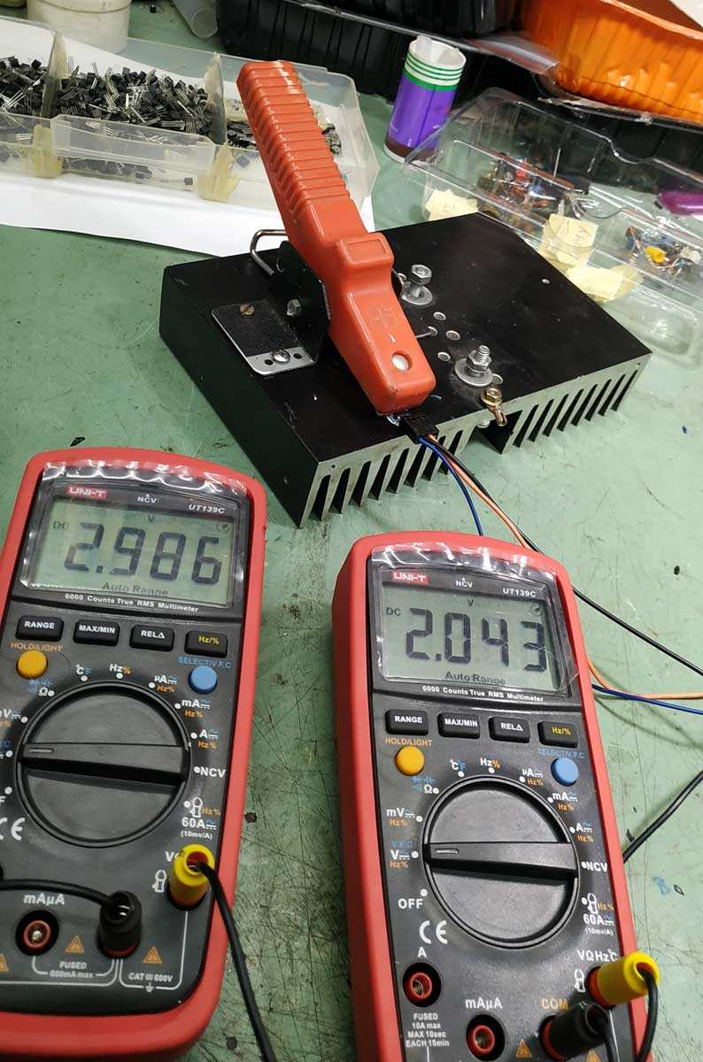
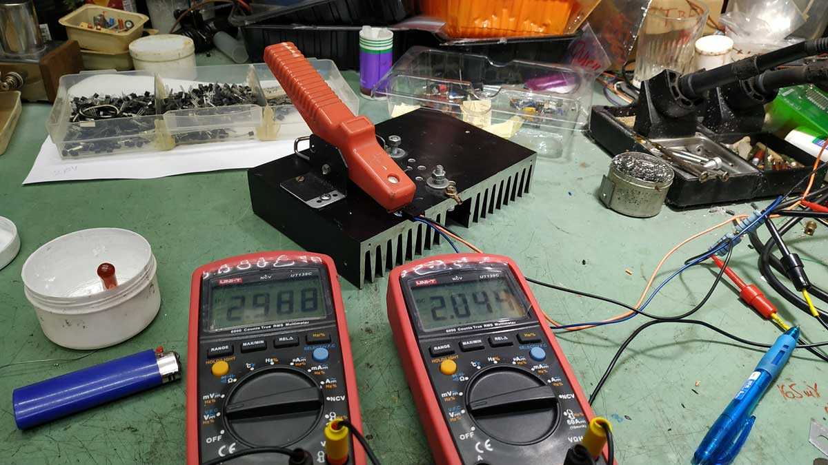
hvali samo displau za temperaturu i tajmere levi master, desni slejv


-
Trenutno na sajtu 0 članova, 0 Skrivenih, 96 Gosta (Pogledaj celu listu)
- There are no registered users currently online
-
Forumska statistika
9.1k
Ukupan broj tema449.7k
Ukupan broj objava -
Statistika članovȃ
3001
Svi članovi5071
Najviše na sajtu